Changing The Lighting - Centre Console Gauges
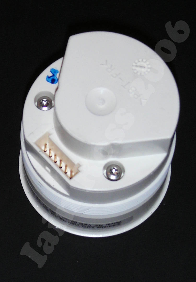
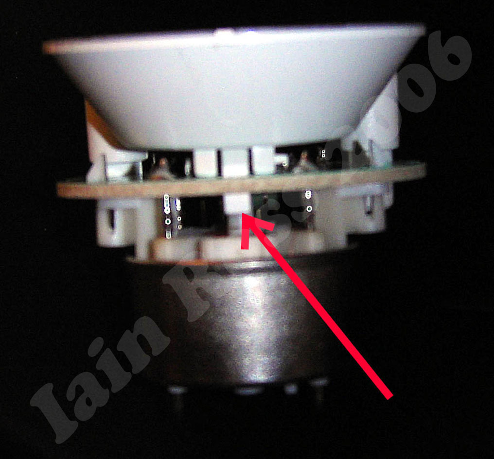
The picture on the left is of the back of the oil temperature gauge The rest of this page concerns changing the lighting of this one. The technique for the clock is broadly similar. This shot shows the rear of the gauge, and clearly visible are the two torx screws that hold it together. These will need to be removed first. I didn't have a torx set handy so used a flat bladed screwdriver.
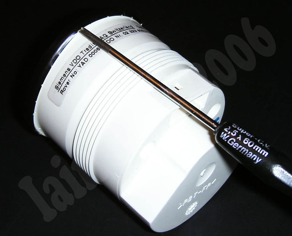
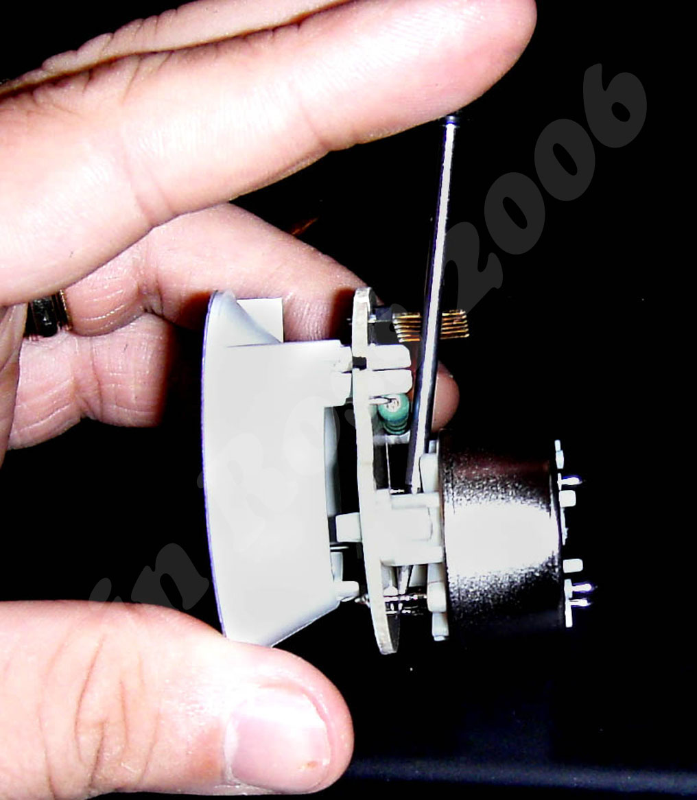
The front window of the gauge is held in place by a retaining ring made of brass, which is crimped around the front of the gauge The only way to remove this is to carefully run a flat bladed screwdriver underneath the ring to prise it off. Removal was quite painstaking and had to be undertaken with care, to avoid damage to the gauge and fingers alike. Once it is off, the internals can be removed from the white plastic housing.

This is what the gauge looks like without the front retaining ring.
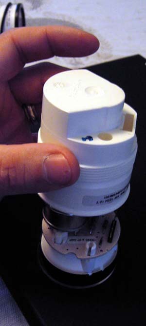
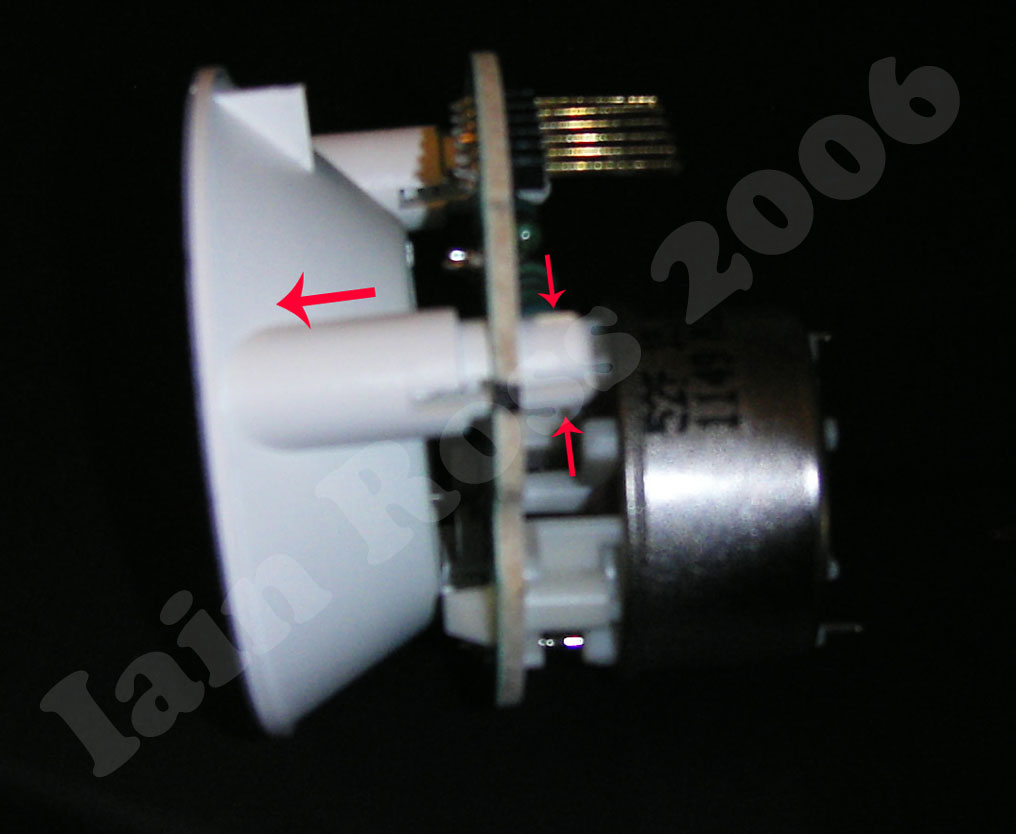
Not really much to say here other than - here is a shot of the white plastic housing being removed!
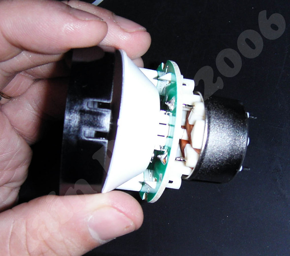
There is a black plastic hood around the dial. This is clipped on with three spring loaded clips. It simply popped off. This reveals the front face of the gauge, and my next job was getting the needle off.

Here is a shot of the front of the oil temperature gauge It was really important that I made an EXACT note of where the needle was at the point I took it off. I made sure that the needle was against the left hand end stop which corresponded to just at the bottom left corner of the 60.
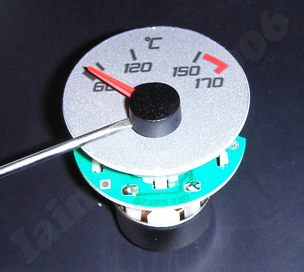
The needle is just pushed on to the metal shaft. It can be carefully levered loose with a flat bladed screwdriver, and released.
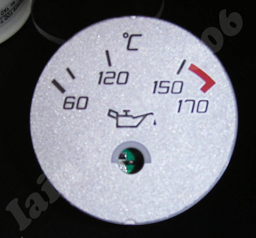
A shot of what the dial looks like without the needle. The green of the printed circuit board (PCB) can be seen below.
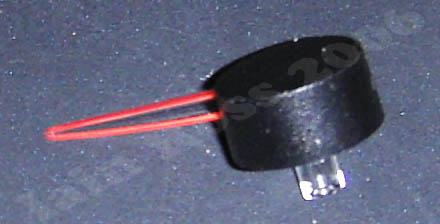
The needle is just clear plastic with red and black paint. This so it glows with light from the LEDs.

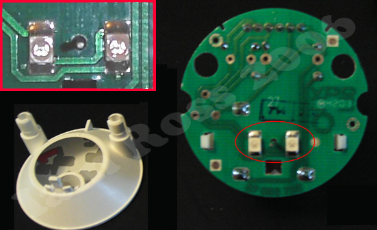
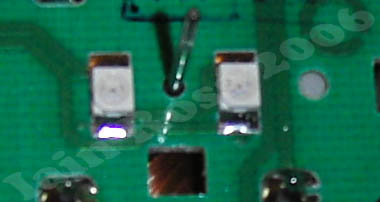
This is the PCB. The two big white rectangles in the centre are magnified in the red box. These are two surface mount orange LEDs. They provide the back lighting for the gauge Below is a closer view of the LEDs. They are surface mount, so are soldered to pads on the PCB. However, because of the gap between the dial face and the PCB it is possible to fit standard 3mm LEDs to these pads. It is important to get the polarity the right way round.
| Images and Text © 2006 Iain Ross |
I accept NO responsibility if you attempt any of the mods on this site. If you mess it up - its your fault!